The structural analysis software RFEM 6 is the basis of a modular software system. The main program RFEM 6 is used to define structures, materials, and loads of planar and spatial structural systems consisting of plates, walls, shells, and members. The program also allows you to create combined structures as well as to model solid and contact elements.
RSTAB 9 is a powerful analysis and design software for 3D beam, frame, or truss structure calculations, reflecting the current state of the art and helping structural engineers meet requirements in modern civil engineering.
Do you often spend too long calculating cross-sections? Dlubal Software and the RSECTION stand-alone program facilitate your work by determining section properties of various cross-sections and performing a subsequent stress analysis.
Do you always know where the wind is blowing from? From the direction of innovation, of course! With RWIND 2, you have a program at your side that uses a digital wind tunnel for the numerical simulation of wind flows. The program simulates these flows around any building geometry and determines the wind loads on the surfaces.
Are you looking for an overview of snow load zones, wind zones, and seismic zones? Then you are in the right place. Use the Geo-Zone Tool to determine quickly and efficiently snow loads, wind speeds, and seismic data according to ASCE 7‑16 and other international standards.
Would you like to try out the capabilities of the Dlubal Software programs? You have the opportunity to do so! The free 90-day full version allows you to thoroughly test all our programs.
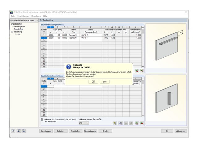
The message shown in Image 01 is displayed if you select the "Minimum distance between stiffeners: 30 ε t" check box in Details and the clear distance between the stiffeners is smaller than this minimum distance: amin. The minimum distance is calculated as follows:
amin = 30 ⋅ ε ⋅ t
where:
t is the thickness of the buckling panel.
In this case, the distance of the stiffeners must be increased in Window "1.2 Stiffeners". For the buckling panel shown in Image 01, the clear distance between the stiffeners is:Δz = z2 - z1 - (t1 + t2) / 2= 890 - 600 - (10 + 10) / 2 = 280 mm
This distance is smaller than the minimum distance:amin = 30 ⋅ ε ⋅ t = 30 ⋅ √(235 / 355) ⋅ 12 = 292.9 mm
Therefore, the position of Stiffener 2 should be entered at leastz2 = z1 + (t1 + t2) / 2 + amin = 600 + (10 + 10) / 2 + 292.9 ≈ 903 mm
This distance is also displayed as information in Window "1.2 Stiffeners" when placing the mouse pointer over Stiffener 2 (Image 02).
If the calculation is also to be performed for a stiffener distance smaller than the minimum distance, the "Minimum distance between stiffeners: 30 ε t" check box must be deactivated (Image 03).
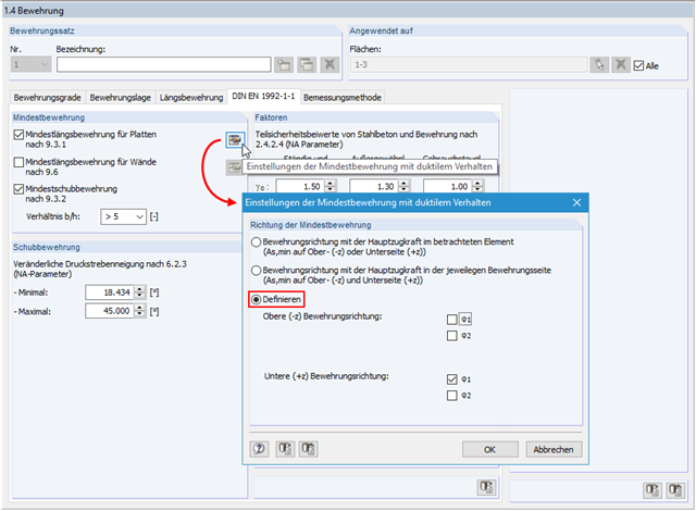
According to EN 1992‑1‑1, Clause 9.3.1, the minimum reinforcement for ensuring ductile behavior of the structural component is to be placed in the main span direction of the plate. In RF‑CONCRETE Surfaces, the "Reinforcement direction with the main tension force in the considered element" option is selected by default. This means that for each element, the program searches for the greatest tension force for each reinforcement direction and for the top surface (-z) and the bottom surface (+z). If the greatest tension force has been found for the individual element, the minimum reinforcement is applied there. If you want to arrange the minimum reinforcement in the principal stress direction for biaxially stressed slabs only, you can specifically control this. To do this, open the "Settings of Min. Reinforcement for Ductile Properties" dialog box. If you select "Define", you can specifically set in which direction and on which side of the structural component the minimum reinforcement should be arranged.